Modbus to LAN converter
Transmission of Modbus communication via Ethernet or Wifi.
| Category: | Accessories |
|---|---|
| EAN: | Choose variant |


Wifi version supports 802.11 b/g/n standard, WEP64 / WEP128 / TKIP / AES security
Ethernet version supports 10/100M Ethernet Auto-Negotiation
Properties
Supported network protocols: TCP, UDP, MQTT, HTTP, WebSocket
Security: TLS v1.2 AES 128Bit DES3
RS485 connection: Baud Rate 600 - 230400 Baud, Data bits 7 / 8, Stop bits 1 / 2, Parity None / Even / Odd
Working temperature: -40 ~ 85°C
Dimensions: 102 x 65 x 27.5 mm
Power supply: 9 ~ 48VDC @ ~200mA
Instructions
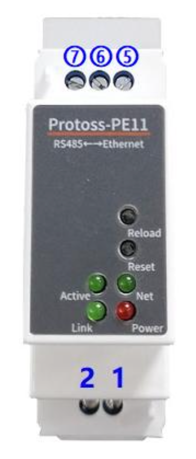
1 .. DC Power Input (VCC+) 9 - 48VDC 2 .. DC Power Input (GND-) 5 .. RS485 (B) 6 .. GND 7 .. RS485 (A) Reload .. Restore to factory settings. For PW11 used also for initialisation of Wi-Fi connection. Reset .. Hardware reset Active - Off: No data transfer - 0.3s Off → 0.9s on: UART TX Output - 0.3s Off → 0.3s On: UART RX Receive Link - On: netp Socket connection OK - Off: no netp Socket connection Net (PE11 Ethernet version) - On: Ethernet connection is OK - Off: No Ethernet connection Net (PW11 Wi-Fi version) - 0.1s Off → 0.1s On: SmartLink Config Mode - 0.3s Off → 3s On: STA mode connected to router or AP mode being connected by other STA
- 0.3s Off → 0.3s On: No Wi-Fi Connection Power
- On: Power input OK
- Off: Power input NG
For Modbus RTU (RS485) communication, connect terminals A and B. Connecting GND is also recommended, if possible. The RS485 interface supports up to 32 devices. The maximum cable length is 1200 meters. A 120 Ohm termination resistor is required if the cable length exceeds 300 meters.
Connecting PW11 to an Existing Wi-Fi Network
- Connect your computer to the Wi-Fi network named PW11_xxx.
- Open a web browser and go to IP address 10.10.100.254.
- If the address is not accessible, use a third-party IP scanner to find the correct one.
-
Log in using the default credentials: Username: admin Password: admin
-
Navigate to System Settings → WiFi Settings and set WiFi Mode to STA.
- Press the Scan button to search for available Wi-Fi networks. Select your desired network and enter its password in the STA KEY field. Click the Submit button to save the settings.
- Go to the Others section and click Restart.
- After the device restarts, reconnect your computer to your original Wi-Fi network.
Configuring PW11 and PE11 (All Versions)
In the TapHome App 1. Go to Settings → IP Scanner. Copy the IP address associated with the manufacturer "Shanghai High-Flying Electronics".
- Use this IP address when creating a new product from a template in Hardware → Modbus TCP. It will be stored in the corresponding Modbus module. In a Web Browser
-
Open the copied IP address in your browser. Log in with the default credentials: Username: admin Password: admin
-
To ensure a stable connection between TapHome and the gateway, either:
- Create a DHCP reservation for this MAC address in your router, or
- Go to System Settings → WAN Settings, disable DHCP, and manually assign a static WAN IP address.
- Match the serial port settings to your Modbus RTU device: Go to Serial Port Settings → Basic Settings and set the correct values for: Baud Rate Data Bit Stop Bit Parity
- In Serial Port Settings → Flow Control Settings, select Half Duplex.
- In Serial Port Settings → Protocol, select Modbus.
- In Communication Settings → Socket Settings, set the Local Port to 502.
- Check if Modbus communication is working properly in Status → Serial Port State.