Ultrasonic tank level sensor
Suitable for retention tanks and septic tanks. Communication via Modbus RTU.
| Category: | Sensors |
|---|


Features
- Measurement range: 0.5 - 20 m
- Accuracy: 0.5%
- Power supply: 12 - 28 VDC
- Communication interface: Modbus RTU (RS485)
- Operating temperature: -40°C ~ 80°C
- Power consumption: < 0.6 W
- Protection: IP65
- Thread: G2, diameter 60 mm
Wiring
- 01 - Modbus RTU (RS485) A
- 02 - Modbus RTU (RS485) B
- 05 - +24 VDC
- 06 - GND
- 08 + 09 - Relay 1
- 10 + 11 - Relay 2
Installation
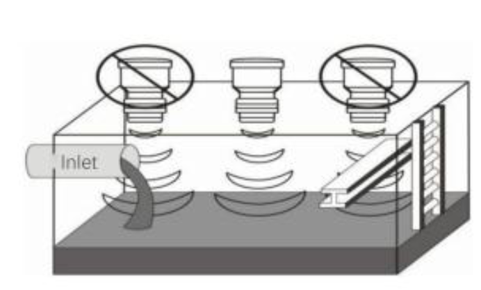
The probe generates an ultrasonic pulse and simultaneously detects the reflected signal, which propagates from the surface of the probe in the shape of a conical wave. There must be no obstruction in this area, and the probe should be installed away from the inlet. The installation position should be selected to ensure there are no obstacles between the probe’s emitting surface and the measured medium.
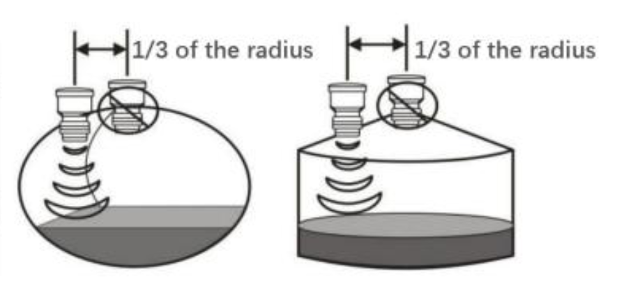
The shape of the tank must be considered when installing the probe. If the probe is not installed correctly, certain tank shapes can cause secondary echoes. This problem most commonly occurs with conical shapes or at the top of spherical tanks. Such shapes can refocus and amplify the reflected signals, leading to incorrect readings. Choosing the proper installation position can prevent this issue. In these cases, move the probe one-third of the tank radius from the center toward the edge.
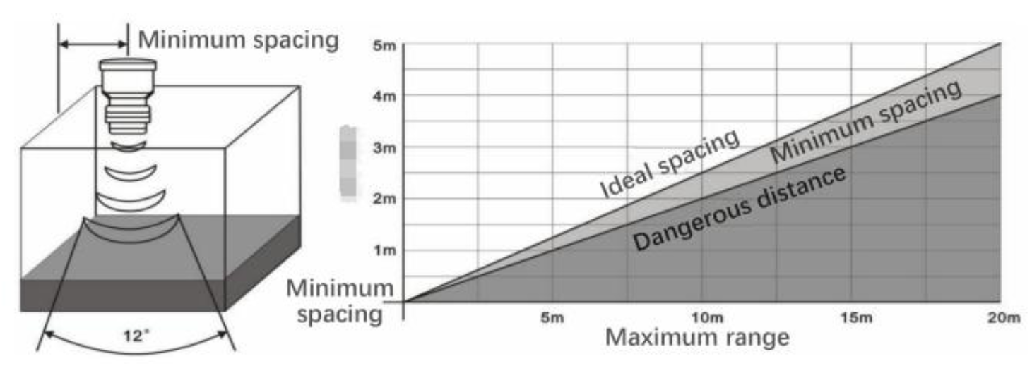
The probe should be installed in such a way as to avoid the propagation of acoustic waves toward the tank walls and to maintain the ideal measurement field shown in the image below. The diagram shows the range and recommended distance of the probe from the tank wall. If the installation distance is less than the recommended value marked by the line, the probe should be installed in the area marked as "minimum spacing." If the distance from the side wall is still less than the "minimum spacing," it is likely that the transmitter will not measure the level correctly.
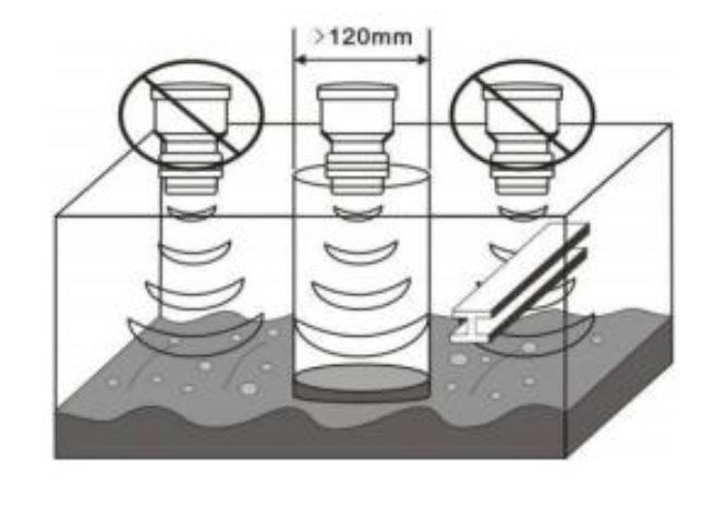
Ultrasonic measurement achieves the best results when the surface of the liquid is calm and wave-free. If the liquid surface contains debris, bubbles, or large fluctuations, a wave guide tube is recommended. The diameter of the guide tube should be greater than 120 mm and must not have any joints.
Configuration
Connect the device to a separate TapHome Bus. Multiple Modbus devices can share the same Modbus RTU bus, provided they use the same connection parameters (Baud rate: 9600, Stop bit: 1, Parity: None, Data bits: 8), and have different Slave IDs.
In the Hardware section, add a Modbus RTU interface and select "Add from template" → ComWinTop → Ultrasonic Level Sensor.
Distance from Surface
No configuration required. This variable shows the measured distance from the sensor to the liquid surface.
Liquid Level Height
To measure the liquid level height, the sensor’s installation height must be configured. This is set via the service action "Installation height" in the service settings of the "Liquid Level Height" variable.
Relay 1, 2
The sensor provides 2 independent relays that operate with hysteresis based on the liquid level. To use them, open the service settings for Relay 1 or 2 and use the service actions "Relay ON" and "Relay OFF" to set two threshold levels for the liquid height.