.svg)
Bus Extender
The Bus Extender connects to the Core via USB and adds 4 bus ports to the system: 2 non-isolated and 2 galvanically isolated. It also includes a USB port for connecting additional devices. All 4 ports support RS485 communication, which is used for TapHome Bus or Modbus RTU communication.
⚠️ Requires OS Image 2.11 or higher. The Bus Extender is not supported on older versions. If you have an older control unit with an older OS Image, contact technical support.
| Category: | Control unit and IO modules |
|---|---|
| EAN: | 8586022930393 |
| naskladnenie: | 10.10.2024 |


Requires OS Image 2.11 or higher. The Bus Extender is not supported on older versions. If you have an older control unit with an older OS Image, contact technical support.
Features
- Power supply: 15-24VDC
- Bus 1, 2: non-isolated RS485 bus (A, B)
- Bus 3, 4: galvanically isolated RS485 bus (A, B, iGND)
- Current consumption without USB OUT connected: max. 60 mA
- Ambient temperature: -20 - 80°C
- DIN rail, 2 modules. Width 36mm, height 59mm.
Installation notes
Isolated bus is required if at least one of the following conditions is met:
- External device is powered from a different source without galvanic isolation (e.g. recovery unit)
- When connecting bus devices, if the bus cable goes outside the building where the Core is installed (e.g. garden house). In this case, separate power supply is required for devices on the isolated bus.
Additional USB devices can be chained using the USB port, for example, up to 3 more Bus Extenders.
If the bus cable is too long and the connected modules have higher power consumption, isolated bus (Bus 3, 4) should be used due to voltage drop. For modules with low power consumption and cable length up to 150m, non-isolated bus (Bus 1, 2) can be used.
On isolated buses, it is recommended to also connect the ground so that A and B are at the correct voltage potential. Communication should work even without iGND connected.
Wiring and bus termination
The Bus Extender has no termination resistor built into any of its ports. The 100 Ω resistor goes between A and B at both ends of the line — depending on where the Extender sits on the line:
- Extender at the end of the line: 100 Ω on the Extender's terminals and 100 Ω at the far end.
- Extender in the middle of the line (two branches): 100 Ω only at the ends of the branches.
This applies to both isolated and non-isolated ports.
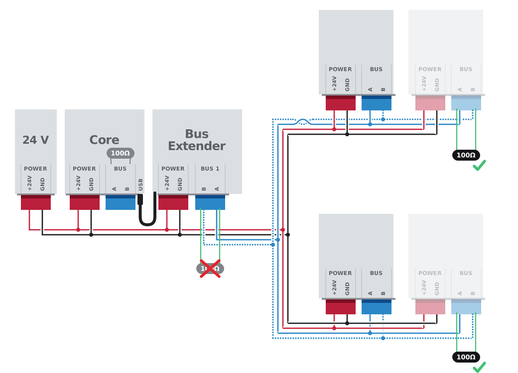
Extender in the middle of a tree (non-isolated Bus 1 port): 100 Ω at the end of each branch, none on the Extender's terminals.
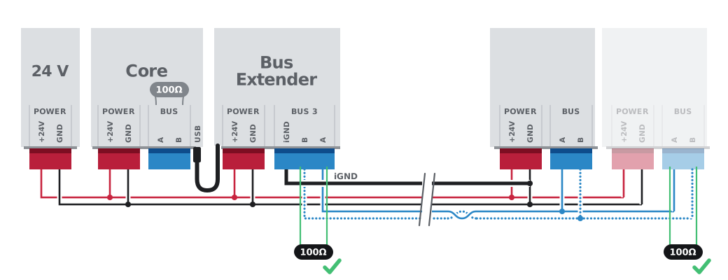
Long cable from the isolated Bus 3 port: the modules are powered from the power supply at the Core, iGND is connected to the GND of the remote modules, 100 Ω at both ends.
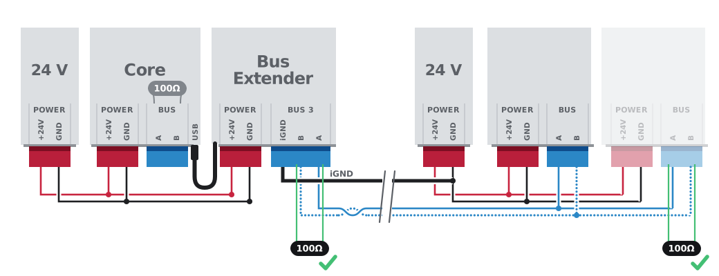
Remote section from a second power supply: only A, B and iGND leave the isolated port, with iGND connected to the GND of the second supply; 100 Ω at both ends.
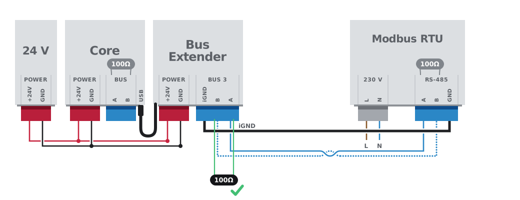
Modbus RTU device with its own power supply: 100 Ω on the Extender's terminals, the device's built-in termination on its side.
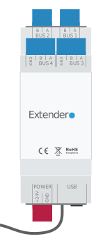
| Connector | Color | Wire | AWG | Torque | Strip | Pins |
|---|---|---|---|---|---|---|
| Power | Red | 0.2–4 mm² | 30–12 | 0.5–0.7 Nm | 6.5–7.5 mm | +24V, GND |
| Bus 1 | Blue | 0.2–4 mm² | 30–12 | 0.5–0.7 Nm | 6.5–7.5 mm | Bus A, Bus B |
| Bus 2 | Blue | 0.2–4 mm² | 30–12 | 0.5–0.7 Nm | 6.5–7.5 mm | Bus A, Bus B |
| Bus 3 | Green | 0.2–4 mm² | 30–12 | 0.5–0.7 Nm | 6.5–7.5 mm | A, B, iGND |
| Bus 4 | Green | 0.2–4 mm² | 30–12 | 0.5–0.7 Nm | 6.5–7.5 mm | A, B, iGND |
| USB OUT | Black | USB Type-A (kábel) | ||||
| USB IN | Black | USB Type-A female |



