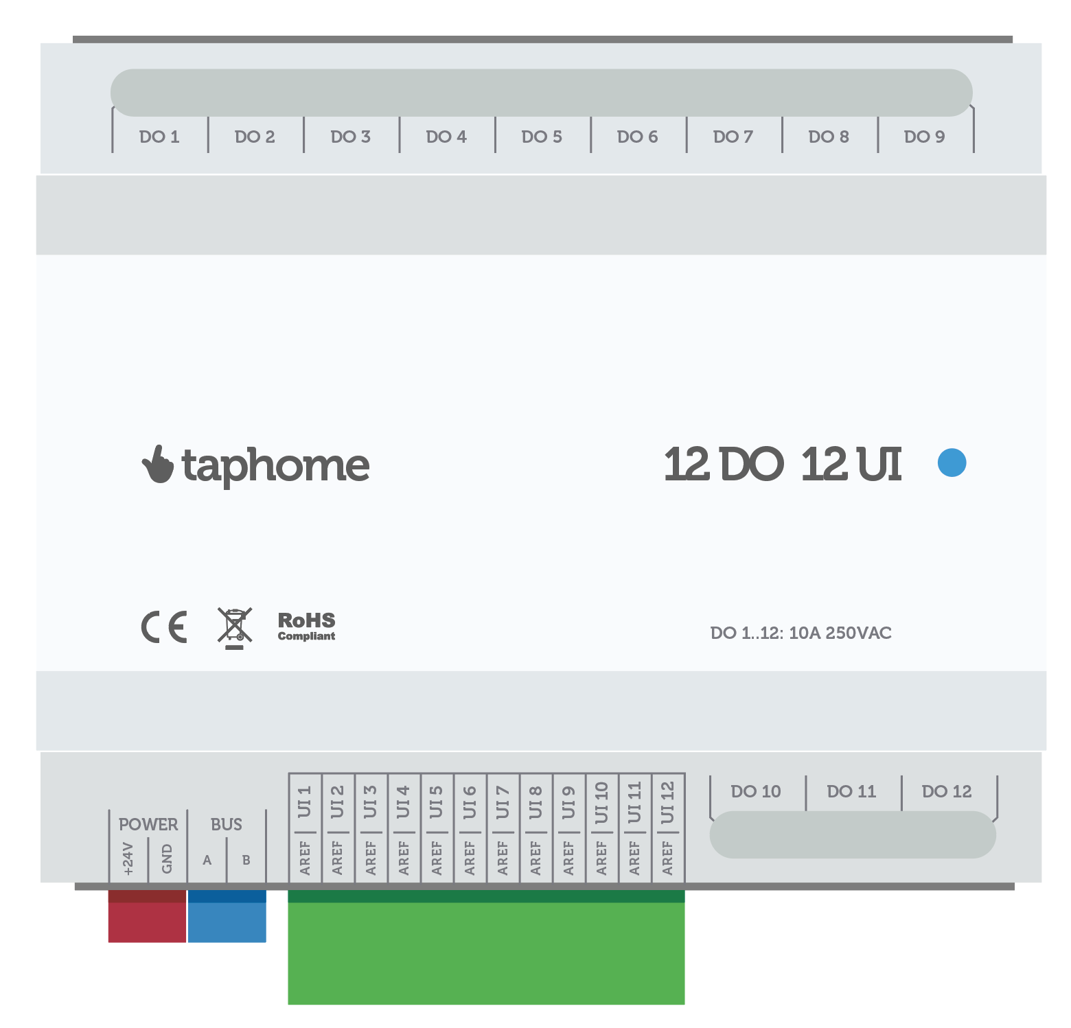
12 DO 12 UI
The most compact module on the market. A combination of 12 universal relay outputs and 12 universal inputs makes it a true space saver and offers exceptional value for money. It also features industrial-grade protection against overheating.
| Category: | Control unit and IO modules |
|---|---|
| EAN: | Choose variant |
| naskladnenie: | 24.7.2024 |


Improvements in Revision 2.0
- Reduced power consumption of relay outputs when ON
- Double-row connector for UI inputs – 2 holes per each UI input
Features
- 12x potential-free relay outputs
- Maximum switching load 16 A
- Maximum continuous load 10 A
- Relay lifetime: 100,000 cycles at max load, 2,000,000 cycles at average load
- Maximum total load 50 A
- Sensors near relays monitor their temperature and shut them down if the temperature exceeds safe levels. Error is shown in the TapHome app.
- Output configurations:
- Independent switched output
- AC blinds with internal blocking of both outputs
- PWM output
- 12 universal inputs configurable for:
- NTC temperature inputs with resistance range 100 Ohm – 100 kOhm ±50 Ohm. Deviation over 1 km Cat6 cable: -0.3 °C at 25 °C. AREF terminal ensures noise-free temperature measurement.
- Button inputs
- Reed / status inputs
- Pulse counter inputs, 200 Hz per channel, 400 Hz sampling rate per channel, pulse width > 2.5 ms
- Analog inputs 0–10 V, voltage range 0–26 VDC, single-ended, 12-bit resolution, 0.1% full-scale accuracy, input impedance > 100 kOhm, 50 dB common-mode rejection at 60 Hz, conversion time 1250 ms
- For 4–20 mA analog input, connect 500 Ohm resistor and set minimum voltage to 2V in Service settings (see gallery screenshot)
- Standby power consumption: 1 W
- Power consumption per active relay: 0.8 W
- Power dissipation per 1 A load: 0.16 W
- Maximum power dissipation at full 20 A load with all relays active: 1 + 0.8 × 12 + 0.16 × 20 = 13.8 W
- Power supply 24 VDC ±10 %
- Enclosure: IP20, operating temperature: -20 °C to 40 °C
- DIN rail, 6 modules. Width 107 mm, height 59 mm
Wiring information
Relay Outputs (DO1–DO12)
Each relay is potential-free. Maximum wire cross-section for screw terminals: 2.5 mm².
Wire the outputs as follows:
- Bring the phase (Lx) from the distribution board to the first screw terminal of the first output.
- Prepare short wire segments ("bridges") and connect them from that same terminal to the common screw of the next output, and continue this for all outputs that share the same phase.
- Connect each second screw of the relay output to its respective load (light, socket, motor, etc.).
- Connect the neutral (N) of each load directly to the neutral busbar, not through the module.
Multiple phases may be used on different groups of outputs if required.
Universal inputs (UI1–UI12)
All inputs are wired UI ↔ AREF